Monthly Archives: September 2026

How Digital Technologies Transform Factory Management

How Digital Technologies Transform Factory Management

Running a modern factory involves far more than keeping machines operating. Production schedules, equipment conditions, quality records, material availability, maintenance work, energy consumption, and delivery plans all influence one another. When information from these areas remains separated, managers may spend a significant amount of time collecting updates before they can understand what is actually happening.

Digital technologies are changing this situation. Connected equipment, industrial networks, data platforms, automation systems, analytics, and digital monitoring tools are creating new ways to organize information across the production environment.

The interesting part is not simply that factories are using more software. The bigger change is how information moves from the shop floor to the people making operational decisions.

A machine can generate a signal. A control system can record it. A data platform can place it alongside production records. An analytical tool can identify a pattern. A manager can then decide whether maintenance, scheduling, quality inspection, or another action is needed.

That creates a much more connected relationship between physical production and factory management.

Why Is Factory Management Becoming More Data-Driven?

Why Is Factory Management Becoming More Data-Driven

A production facility can generate thousands of individual observations during normal operation.

Machines have operating states. Sensors detect physical conditions. Controllers record process events. Quality systems collect inspection results. Maintenance teams document repairs. Warehouses track material movement. Production planners manage orders and schedules.

None of these information sources is particularly useful if it remains isolated.

Consider a simple production delay.

A machine stops unexpectedly.

The immediate problem appears to belong to production. But the consequences may extend to several departments:

Equipment Stop → Production Delay → Schedule Change → Material Requirement Change → Delivery Planning

A connected information environment makes this chain easier to see.

Instead of treating the machine stop as an isolated incident, managers can examine what happened before the event, which process was affected, what work was interrupted, and what other activities may now need adjustment.

This is one of the practical reasons digitalization has become an important subject in manufacturing.

1. From Periodic Reports To Current Production Information

Traditional factory reporting often depends on information collected after production activity has already taken place.

A shift report might explain what happened during the previous working period. A maintenance record might be updated after a repair. Quality information may become available after inspection.

These records remain useful, but they provide a historical view.

Connected systems can provide information much closer to the time when an event occurs.

Managers may be able to see:

  • Equipment operating status
  • Production progress
  • Machine interruptions
  • Process conditions
  • Quality events
  • Material movement
  • Maintenance activities
  • Production schedule changes

The practical difference is significant.

Instead of asking only, "What happened yesterday?", a production manager can also ask, "What is happening now, and does it affect today's plan?"

Information Flow In A Connected Factory

Production SourceInformation GeneratedPossible Management Use
MachinesOperating statusProduction monitoring
SensorsProcess conditionsProcess review
PLC systemsControl statesEquipment diagnosis
Inspection systemsQuality resultsQuality analysis
Maintenance recordsRepair historyMaintenance planning
Warehouse systemsMaterial statusProduction planning
Scheduling systemsOrder progressCapacity management

The objective is not to collect information simply because technology makes collection possible.

Useful information is information that helps someone make a decision.

2. Connected Equipment Creates A More Complete Picture

Machines have always produced signals and operating information.

The difference today is that more of this information can be collected, stored, organized, and compared.

A production line may contain:

  • Position sensors
  • Temperature sensors
  • Pressure sensors
  • Motor monitoring devices
  • PLCs
  • Drives
  • Industrial network equipment
  • Inspection systems
  • Control panels

Each device provides a different piece of information.

When these pieces are connected, a manager can move from a simple question such as "Is the machine running?" toward more useful questions:

  • How has the machine been operating?
  • When did the condition change?
  • Which process was active?
  • Has the same event occurred before?
  • Is the issue isolated or recurring?
  • Does the condition correspond with a quality problem?

This shift from isolated status information to historical context can make operational analysis more useful.

3. Production Data Can Connect Different Departments

Production Data Can Connect Different Departments

Manufacturing rarely works as a collection of independent teams.

Production depends on maintenance.

Maintenance depends on equipment information.

Quality depends on process conditions.

Planning depends on production capacity.

Purchasing depends on material requirements.

Logistics depends on production progress.

A change in one area can therefore create consequences elsewhere.

Digital systems can help connect these relationships.

For example, when equipment availability changes, production planning can receive updated information. When production schedules change, material requirements may also change. When a quality issue is identified, engineers can review the associated production conditions.

This creates a broader operational chain:

Production → Quality → Maintenance → Planning → Materials → Logistics

The factory becomes easier to manage when each department can work with information that reflects the same underlying situation.

4. Maintenance Is Becoming More Condition-Aware

Maintenance has traditionally included scheduled servicing and corrective repairs.

Digital monitoring adds another source of information: equipment condition.

A machine may gradually change before a noticeable failure occurs. Changes in vibration, temperature, operating cycles, alarms, or other conditions can provide useful clues.

That does not mean a digital system can predict every equipment problem.

It means maintenance teams have more evidence available when deciding what deserves inspection.

A practical maintenance process may look like this:

Monitor → Detect Change → Investigate → Inspect → Repair Or Adjust → Verify

Historical records can also help technicians recognize recurring patterns.

For example, if a particular machine repeatedly develops an abnormal condition after a certain production sequence, that relationship may deserve closer investigation.

The value lies in connecting the event with its operating context.

5. Production Planning Can Respond To Actual Conditions

A production schedule is a plan, not a guarantee.

Equipment availability, material supply, quality issues, maintenance work, and changing order priorities can all affect whether the original plan remains practical.

Without current production information, planners may discover a problem only after it has already affected the schedule.

Connected systems can shorten this information gap.

A basic relationship looks like this:

Planned Production → Actual Production → Variance → Schedule Review

Suppose a machine operates below its planned availability. The issue may affect only one order, or it may influence several downstream activities.

When production status is available sooner, planners have more opportunity to examine alternatives.

Digitalization therefore does not necessarily mean that software creates the production schedule automatically.

Sometimes the more useful improvement is simply knowing when the original plan no longer matches reality.

6. Quality Management Gains Process Context
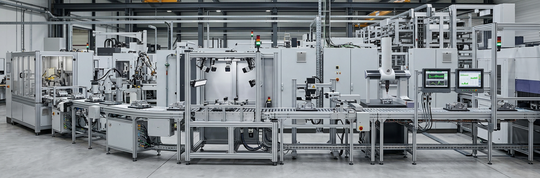
A quality problem is not always visible at the moment it begins.

A product may pass through several stages before an abnormal result is discovered.

If production records, machine conditions, material information, and inspection results are connected, engineers can investigate the process with more context.

A useful chain is:

Material → Process Conditions → Equipment State → Production Event → Inspection → Quality Result

This can help answer questions such as:

  • Did the issue occur during a particular process stage?
  • Was equipment behavior unusual at the time?
  • Did the same condition appear in previous production?
  • Was a material or process change involved?
  • Does the problem occur repeatedly under similar conditions?

The goal is not to replace quality engineering with software.

It is to make the investigation less dependent on isolated records.

7. Digital Dashboards Change How Managers Consume Information

Factories can generate more information than one person can reasonably review.

That creates another challenge.

More data does not automatically mean better management.

If a dashboard contains hundreds of indicators without clear priorities, managers may struggle to determine which information requires action.

A useful operational display should answer practical questions.

AreaUseful Question
ProductionAre current activities progressing as planned?
EquipmentWhich assets need attention?
QualityAre unusual trends appearing?
MaintenanceWhat work is currently pending?
MaterialsIs required material available?
PlanningDoes the current schedule still match conditions?
EnergyAre consumption patterns changing?

Good visualization is therefore part of digital transformation.

The purpose of a dashboard is not to display technology.

Its purpose is to reduce the effort needed to understand the factory.

8. Automation And Digital Management Serve Different Purposes

Automation and digital management are closely related, but they are not the same thing.

An automated control loop might work like this:

Sensor → Controller → Output → Actuator

The system detects a condition and responds according to programmed logic.

A management information loop is broader:

Machine Data → Data System → Analysis → Management Decision → Operational Action

One deals mainly with controlling a physical process.

The other deals with understanding and coordinating that process.

A factory can therefore have highly automated equipment while still relying on disconnected spreadsheets, reports, or manual communication for management activities.

Digital transformation addresses this information layer.

9. Industrial Connectivity Is The Foundation

For digital systems to work effectively, equipment needs a practical way to exchange information.

Industrial connectivity can involve:

  • Control networks
  • Industrial Ethernet
  • Remote I/O
  • Sensors
  • Gateways
  • Data collection systems
  • Edge devices
  • Factory network infrastructure

Older equipment can create a particular challenge.

A production facility may contain machines installed at different times, using different control architectures and communication methods.

The result can be a mixed environment.

A Typical Integration Challenge

Existing SituationDigitalization Challenge
Older machineLimited data access
Different control systemsData compatibility
Separate databasesInformation fragmentation
Manual recordsDelayed updates
Isolated equipmentLimited visibility
Multiple departmentsDifferent data structures

This is why digital factory projects often involve integration work rather than simply installing a new application.

10. Edge Computing Brings Processing Closer To Equipment

Not every piece of industrial information needs to travel to a central system before it can be processed.

Edge computing places processing capability closer to machines and local control environments.

This can support applications that require:

  • Local data processing
  • Rapid response
  • Filtering of machine information
  • Local condition monitoring
  • Reduced dependence on external connections

A simple architecture could look like:

Machine → Local Processing → Relevant Information → Factory System

The local layer can handle information that does not need to be transferred in its raw form.

This can be particularly useful when equipment generates large volumes of operational data.

11. Artificial Intelligence Adds New Analytical Possibilities

Artificial intelligence is receiving increasing attention in manufacturing because industrial environments can generate large datasets.

Potential applications include:

  • Detecting unusual equipment behavior
  • Identifying production patterns
  • Supporting quality analysis
  • Reviewing maintenance history
  • Assisting production planning
  • Examining energy consumption
  • Supporting process analysis

However, the quality of the result depends heavily on the quality and context of the underlying information.

A useful sequence is:

Reliable Data → Correct Context → Appropriate Model → Human Review → Factory Action

This point is easy to overlook.

An algorithm may identify a pattern, but engineers still need to determine whether that pattern has a meaningful physical explanation.

Industrial knowledge remains important because manufacturing processes involve real equipment, materials, operating conditions, and production constraints.

12. Digital Twins Can Support Planning And Simulation

A digital twin is a digital representation of a physical asset, process, or production environment.

In manufacturing, such models can support questions that are difficult or expensive to test directly on the production floor.

Possible applications include:

  • Production layout planning
  • Equipment placement
  • Process analysis
  • Capacity planning
  • Maintenance planning
  • Production flow studies
  • Scenario evaluation

For example, before changing a production layout, engineers can examine material movement and equipment relationships in a digital environment.

The value comes from answering a practical question.

A digital model should not be created simply because having one appears technologically attractive.

13. Inventory Management Becomes More Closely Linked To Production

Material management is another area affected by connected information.

Inventory levels are influenced by production schedules, material consumption, incoming supply, quality holds, and changes in production priorities.

A simplified relationship is:

Production Plan → Material Requirement → Inventory Status → Purchasing Activity

When the production plan changes, material requirements may change with it.

When equipment becomes unavailable, planned material consumption may also shift.

When quality issues place material on hold, available inventory can change without a corresponding physical movement.

Connecting these events helps managers understand why inventory conditions change rather than simply seeing the final quantity.

14. Energy Information Can Become Part Of Production Analysis

Energy management is increasingly connected with production data.

Rather than viewing energy consumption as a completely separate utility issue, factories can compare it with operating conditions.

Questions may include:

  • Which production areas consume more energy?
  • How does consumption change with machine activity?
  • What happens when equipment is idle?
  • Are energy patterns changing over time?
  • Do unusual operating conditions correspond with changes in consumption?

The useful insight often comes from the relationship between energy and production.

A consumption figure without context tells only part of the story.

15. Digital Tools Can Help Identify Production Bottlenecks

A bottleneck is not always caused by the machine with the longest processing time.

Delays can also come from:

  • Material movement
  • Changeovers
  • Quality inspection
  • Equipment availability
  • Maintenance activities
  • Waiting between process stages
  • Production scheduling
  • Limited downstream capacity

Connected production records can make these relationships easier to examine.

For example:

Process A → Process B → Inspection → Process C

If Process C regularly waits for inspection results, increasing the speed of Process B may not solve the real constraint.

Digital analysis can help management look at the entire production flow rather than focusing on one machine.

16. Factory Digitalization Also Changes Decision-Making

The real effect of connected technology appears when information changes what people do.

Consider several examples.

Equipment Decision

Historical machine conditions show repeated abnormal behavior.

Response: Maintenance investigates the pattern before it becomes a larger production issue.

Planning Decision

Current equipment availability differs from the original schedule.

Response: Production planning reviews the affected sequence.

Quality Decision

Inspection results repeatedly correspond with a particular process condition.

Response: Engineering investigates the process relationship.

Inventory Decision

Production requirements change.

Response: Material planning reviews purchasing and warehouse requirements.

In each example, the technology is not the final result.

The decision is the result.

17. Cybersecurity Must Grow Alongside Connectivity

Connecting more factory equipment also creates more communication paths.

That makes cybersecurity an important part of digitalization.

Areas that deserve attention include:

  • Network segmentation
  • User access
  • Device management
  • Software updates
  • Backup procedures
  • Remote connections
  • Data protection
  • System monitoring
  • Incident response

Industrial environments have different requirements from ordinary office networks.

A change to a control system can influence physical equipment, production continuity, or process behavior.

For that reason, digital systems should be introduced with cooperation between automation engineers, IT teams, maintenance personnel, and factory management.

18. People Still Provide Essential Industrial Knowledge

Digital transformation does not remove the need for experienced technicians, operators, engineers, or managers.

In fact, their knowledge can become more valuable when combined with better information.

An experienced technician may notice an unusual sound, vibration, sequence behavior, or machine response long before a formal alarm appears.

A digital monitoring system can then provide supporting information.

This creates a useful combination:

Operator Experience + Equipment Data + Engineering Analysis

Technology provides additional visibility.

People provide context.

The strongest operational decisions often require both.

19. Start With A Factory Problem, Not A Technology Trend

One of the easiest ways to make digitalization complicated is to begin by asking, "Which new technology should we install?"

A better question is:

"Which factory problem needs better information?"

Possible starting points include:

  • Production status is difficult to track
  • Maintenance problems recur without clear patterns
  • Quality investigations take too long
  • Production schedules frequently become outdated
  • Inventory information is fragmented
  • Machine data is difficult to access
  • Management reports require excessive manual work

Once the problem is clear, the technology becomes easier to evaluate.

A Practical Planning Framework

QuestionPurpose
What problem needs attention?Define the actual objective
What information is missing?Identify data requirements
Where does that information originate?Locate equipment and systems
Who needs the information?Define users
What decision will it support?Define the use case
What action follows the decision?Connect data to operations
How will the result be reviewed?Support continuous improvement

This prevents a common problem: collecting large amounts of data without a clear operational purpose.

20. A Step-By-Step Path Toward Digital Factory Management

A factory does not need to digitize every department at the same time.

A staged approach can make implementation easier to control.

Step 1: Map The Existing Environment

Identify production equipment, control systems, data sources, maintenance workflows, quality systems, and reporting methods.

Step 2: Find The Information Gaps

Determine where managers and engineers lack timely or reliable information.

Step 3: Select A Practical Use Case

Choose a problem with a clear operational purpose.

Step 4: Connect Relevant Equipment

Collect information from the machines and systems directly related to that use case.

Step 5: Organize The Data

Create consistent definitions and structures so information can be compared.

Step 6: Build Useful Visualization

Present information in a form that production, maintenance, engineering, and management teams can understand.

Step 7: Add Analysis

Use historical and current information to identify trends, abnormal conditions, and relationships.

Step 8: Connect Insights To Actions

Define what happens when the system identifies a condition that requires attention.

Step 9: Review And Expand

Once the process proves useful, consider whether the same approach can support another factory function.

This staged method keeps technology connected to actual manufacturing needs.

What Should Factory Managers Consider Before Digitalizing?

Before introducing a new digital system, several practical questions deserve attention.

Data availability: Is the required information already generated by existing equipment?

Data quality: Can the information be trusted and interpreted correctly?

System compatibility: Can existing machines and software exchange information?

User needs: Who will actually use the system?

Operational response: What happens when the system identifies an abnormal condition?

Maintenance: Who will maintain the digital infrastructure?

Security: How will access and connected devices be managed?

Scalability: Can the solution support future production changes?

A technology project becomes much more useful when these questions are answered before implementation begins.

The Factory Is Becoming A Connected Information System

The physical factory remains at the center of manufacturing.

Machines still perform mechanical work. Sensors still measure physical conditions. Controllers still manage sequences. Operators and engineers still make practical decisions.

What is changing is the information layer surrounding these activities.

A connected manufacturing environment can create a continuous loop:

Physical Process

Data Collection

Information Integration

Analysis

Management Decision

Operational Action

New Production Data

The final stage feeds information back into the system.

That creates a cycle rather than a one-way report.

Five Changes Worth Watching

The development of digital factory management can be understood through five broad changes.

Traditional ApproachConnected Approach
Periodic reportingMore current operational visibility
Isolated equipment dataConnected equipment information
Reactive maintenanceCondition-informed maintenance
Separate departmental recordsCross-functional information
Manual analysisData-supported analysis

These changes do not happen automatically.

They depend on suitable infrastructure, clear processes, reliable data, and people who know how to use the information.

What Will Digital Factory Management Look Like In Practice?

The future factory is unlikely to be defined by one piece of technology.

Instead, several layers will work together.

At the equipment level, sensors and controllers will continue collecting process information.

At the connectivity level, industrial networks will move information between machines and systems.

At the data level, platforms will organize information from different sources.

At the analytical level, software will identify patterns and unusual conditions.

At the management level, people will use that information to make decisions about production, maintenance, quality, materials, and planning.

The result is not a factory where technology makes every decision.

It is a factory where important decisions can be supported by information that is easier to access, compare, and understand.

Digital technologies are changing factory management by connecting physical production with a wider information environment. Sensors, controllers, networks, data systems, analytics, monitoring tools, and digital models each contribute a different layer.

The real transformation happens when these layers work together.

A machine condition can become maintenance information. A production delay can become planning information. A quality result can be connected with process conditions. An inventory change can be understood alongside production requirements.

This approach gives manufacturers a clearer way to understand what is happening across the factory and why it is happening.

The goal is not to digitize everything simply because digital tools are available. A more practical approach is to identify where information is missing, connect the relevant systems, and turn that information into decisions that improve everyday factory operations.

That is where digital technology becomes part of factory management rather than simply another layer of factory equipment.

Industrial Troubleshooting Methods for Automation Systems

Industrial Troubleshooting Methods for Automation Systems

Industrial automation systems rarely fail for just one obvious reason. A machine may stop because a sensor is not detecting a position, an input signal is missing, a control condition has not been satisfied, a network connection has dropped, or an actuator is not responding as expected. In other cases, the equipment appears to be running normally while producing inconsistent results.

That is why Industrial Troubleshooting Methods For Automation Systems should not begin with replacing a PLC or changing program logic. A useful investigation starts with the actual symptom and then follows the control path step by step. Power, field devices, I/O, control logic, communication, actuators, and process conditions all form part of the same system.

A structured method also makes troubleshooting easier to repeat. Instead of relying on individual experience or guesswork, technicians can compare what the system should be doing with what it is actually doing.

Why Automation Troubleshooting Requires A Systematic Method

An automated machine is a chain of connected functions.

A typical sequence may look like this:

Operator Command → Controller → Output Signal → Actuator → Machine Movement → Sensor Feedback → Controller

A fault anywhere along this path can create a similar symptom.

For example, if a conveyor does not start, the cause could be:

  • The start command never reached the controller
  • A safety condition is preventing operation
  • A sensor has not reached the expected state
  • An input channel is not receiving the field signal
  • Control logic is waiting for another condition
  • The output command is not being generated
  • The output circuit has a problem
  • The motor control device is not responding
  • A communication connection has been interrupted
  • A mechanical condition is preventing movement

The visible symptom is therefore only the beginning of the investigation.

A Simple Troubleshooting Principle

Do not ask only, "What component failed?" Ask, "Where did the expected sequence stop?"

That question changes the entire troubleshooting process.

1. Start With The Actual Symptom

Before opening a control cabinet or changing software, define what is happening.

There is an important difference between an observation and an assumption.

ObservationAssumption
Motor does not startMotor is defective
Sensor changes state but machine does not respondPLC program is wrong
HMI shows a communication alarmNetwork switch has failed
Valve command is active but valve does not moveOutput module is defective
Machine stops during one sequenceController has a fault

The left side gives technicians something that can be tested. The right side may send the investigation toward a component that is actually working.

Useful questions include:

  • When did the problem begin?
  • Does it happen every cycle or only occasionally?
  • Did anything change before the fault appeared?
  • Does the machine stop at the same point?
  • Is the fault limited to one station?
  • Are other machines affected?
  • Does restarting temporarily change the behavior?

These details can significantly narrow the search area.

2. Check The Control System From The Outside In

One practical approach is to move from the physical process toward the controller rather than immediately opening the programming environment.

A useful diagnostic order is:

Process → Field Device → Wiring → I/O → Controller → Logic → Output → Actuator

This sequence follows the actual flow of information through an automated machine.

Suppose a cylinder is not moving.

Instead of immediately checking the control program, ask:

  1. Is the machine requesting the movement?
  2. Is the required condition satisfied?
  3. Does the relevant sensor show the expected position?
  4. Does the controller receive that signal?
  5. Does the logic generate the output command?
  6. Does the output module respond?
  7. Does the actuator receive the command?
  8. Can the mechanical system move freely?

Each answer removes one part of the system from consideration.

That is the value of structured troubleshooting: the investigation becomes narrower with every verified condition.

3. Power Problems Can Create Confusing Symptoms

Power-related faults do not always result in a completely dead machine.

An automation system may continue operating while one module, field device, or control circuit behaves incorrectly. Intermittent behavior can be particularly difficult because the system may appear normal when a technician arrives.

Initial checks should consider:

  • Control power availability
  • Protective devices
  • Loose terminals
  • Power distribution
  • Module status indicators
  • Grounding conditions
  • Signs of overheating
  • Recent electrical work
  • Repeated power interruptions

The important point is not simply whether power exists.

The question is whether the correct part of the system is receiving the expected electrical condition.

What Power Checks Can Reveal

SymptomPossible Area To Investigate
Entire control system inactiveIncoming control power or protection
One module inactiveLocal supply or connection
Intermittent controller behaviorPower quality or connection
Field device inactiveDevice supply or wiring
Communication device offlineDevice power or network connection

These are starting points rather than fixed diagnoses. The same symptom can have different causes depending on the system architecture.

4. Sensors Are Often The Starting Point For Signal Problems

Automation depends heavily on feedback.

Sensors tell the controller whether a component has reached a position, whether material is present, whether a condition has changed, or whether a process step can continue.

When a machine stops unexpectedly, sensor feedback deserves careful attention.

Consider a simple sequence:

Part Detected → Clamp Activated → Position Confirmed → Processing Starts

If the position confirmation never arrives, the controller may correctly refuse to continue.

The machine has not necessarily failed. It may simply be waiting for information that never became available.

Sensor Troubleshooting Questions

  • Is the sensor physically aligned?
  • Is the sensing surface clean?
  • Is the target reaching the expected position?
  • Does the device receive power?
  • Does its output change when the process condition changes?
  • Does the signal reach the I/O module?
  • Does the controller see the same state?
  • Does the program interpret that state correctly?

This approach separates a physical sensing problem from a wiring problem and then from a software interpretation problem.

5. I/O Troubleshooting Connects The Physical And Digital Worlds

Input and output modules sit between field equipment and controller logic.

That makes them an important diagnostic boundary.

A field sensor can operate correctly while its signal fails to reach the controller. Likewise, the controller can generate an output command while the field device receives no usable signal.

A useful comparison is:

Point To CompareWhat It Tells You
Physical deviceWhether the field condition exists
Field wiringWhether the signal can travel
I/O indicatorWhether the module sees the signal
Controller inputWhether the software receives the signal
Program conditionWhether the signal is being used
Controller outputWhether a command is generated
Output circuitWhether the command reaches the load
ActuatorWhether the machine responds

This creates a diagnostic bridge from the machine to the control program.

If the sensor changes but the PLC input does not, the investigation should remain around the field signal path.

If the PLC input changes correctly but the expected logic does not respond, attention can move toward control conditions.

If the output command is present but the machine remains inactive, the investigation moves downstream.

6. Do Not Ignore Interlocks And Permissive Conditions

A machine can appear ready while still being prevented from running by an interlock.

Interlocks exist to control sequence conditions and protect equipment from operating in an unsuitable state. From a troubleshooting perspective, they can also explain why an output never becomes active.

For example, a motor start command may depend on several conditions:

  • Machine in automatic mode
  • Required guard condition satisfied
  • Previous process step complete
  • Material detected
  • No active fault condition
  • Downstream equipment available
  • Required feedback received

Only one missing condition may prevent the entire sequence from continuing.

A Better Question

Instead of asking:

"Why does the motor not start?"

Ask:

"Which condition prevents the motor start command from becoming active?"

That is a much more useful diagnostic question.

7. Use PLC Diagnostics As Evidence, Not As A Guessing Tool

PLC diagnostics can provide valuable information about the current state of an automation system.

Depending on the control architecture, technicians may review:

  • Controller status
  • Module status
  • Fault history
  • Input states
  • Output states
  • Program conditions
  • Communication status
  • Alarm history
  • Sequence states
  • Process variables

Online monitoring can help show where the expected sequence differs from actual operation.

However, a diagnostic message should not automatically be treated as the root cause.

For example, a communication alarm may be the result of a power problem at a remote device. The communication fault is real, but it may only be a symptom of another failure.

This distinction is important:

Alarm = What The System Detected

Root Cause = Why The Condition Occurred

Good troubleshooting works toward the second question.

8. Output Troubleshooting Should Follow The Command Path

When an actuator does not respond, trace the output from the controller to the physical device.

The investigation can follow this path:

Program Condition → Output Command → Output Module → Wiring → Interface Device → Actuator → Mechanical Response

This method prevents technicians from treating the actuator as the only possible problem.

A valve, relay, motor control device, or other actuator may be functioning normally while the control signal is missing.

Conversely, the PLC may show the expected output state while a downstream problem prevents physical operation.

Common Output Investigation Areas

  • Output command state
  • Module status
  • Wiring condition
  • Terminal connections
  • Protection devices
  • Interface components
  • Actuator condition
  • Mechanical obstruction
  • Process-related restrictions

The key is to identify the first point where expected behavior becomes actual behavior.

That point is often more valuable than the final failed component.

9. Industrial Communication Faults Need Layered Troubleshooting

Modern automation systems rely on communication between controllers, HMIs, remote I/O, drives, monitoring systems, and other devices.

When communication fails, the temptation is often to restart everything.

That may restore operation temporarily, but it does not explain why the connection failed.

A better method separates the problem into layers.

Diagnostic LayerQuestions
Device powerIs the connected equipment operating?
Physical connectionAre cables and connectors intact?
Network equipmentAre connected ports behaving normally?
AddressingAre devices configured consistently?
Communication relationshipAre devices establishing the expected connection?
Data exchangeIs valid information being transferred?
Control logicIs the received data being interpreted correctly?

A successful physical connection does not necessarily mean that the application is communicating correctly.

Likewise, a communication alarm does not automatically mean that the network hardware has failed.

This is why communication troubleshooting should move from the physical layer toward the control application.

10. Intermittent Faults Require A Different Approach

Some of the hardest automation faults disappear before they can be observed.

A machine may run correctly for hours and then stop once. After a restart, everything appears normal.

Replacing components at random is rarely a useful response.

Instead, record patterns.

Track These Details

  • Time of occurrence
  • Machine operating state
  • Process step
  • Alarm history
  • Environmental conditions
  • Recent maintenance
  • Recent configuration changes
  • Whether the fault disappears after restart
  • Whether the same station is involved repeatedly

Patterns often reveal relationships that a single observation cannot.

For example, if a communication fault appears only when another machine begins operation, electrical interference or shared infrastructure may deserve investigation. If a sensor fault occurs after a certain mechanical movement, alignment or vibration may become more relevant.

The goal is to turn an intermittent event into a repeatable diagnostic clue.

11. Separate Control Faults From Mechanical Problems

Not every automation problem is an electrical or software problem.

A controller can issue the correct command while the machine still fails to move.

Consider a conveyor that receives a valid run command but does not move. Possible areas include:

  • Mechanical obstruction
  • Drive or motor condition
  • Coupling problems
  • Excessive mechanical resistance
  • Misalignment
  • Material-related loading
  • Actuator condition

The troubleshooting process should therefore cross the boundary between controls and mechanics.

A Useful Rule

If the control system says "go," verify whether the physical system can actually go.

This simple distinction prevents control technicians from spending too much time changing logic when the real problem is mechanical.

12. Compare Normal Operation With Fault Operation

One of the strongest troubleshooting techniques is comparison.

If another machine, station, sequence, or cycle operates correctly, use it as a reference when appropriate.

Compare:

  • Input states
  • Output states
  • Sequence position
  • Alarm conditions
  • Communication status
  • Sensor feedback
  • Actuator response
  • Process conditions

The comparison does not prove that the healthy system is configured identically. It simply gives technicians another set of observations.

That can make unusual conditions easier to recognize.

13. Avoid Changing Too Many Things At Once

Troubleshooting becomes difficult when several variables are changed simultaneously.

Suppose a machine has a communication fault. A technician replaces a cable, restarts the controller, changes a configuration setting, and modifies a program condition.

The machine starts working again.

What caused the problem?

There is no reliable answer.

A more controlled approach is:

Observe → Test → Record → Change One Condition → Test Again

This creates a clearer relationship between action and result.

It also makes later root-cause analysis easier.

14. Root Cause Analysis Begins After The Machine Recovers

Getting the machine running again is not always the end of troubleshooting.

There are two separate questions:

  1. What restored operation?
  2. Why did the fault occur?

Those answers may be different.

For example, restarting a controller may restore a communication connection. But the restart does not explain why communication was interrupted.

Likewise, replacing a sensor may restore a machine, but the investigation may still need to determine whether the sensor failed because of wear, installation conditions, contamination, vibration, wiring stress, or another factor.

A Useful Root Cause Record

ItemRecord
Original symptomWhat the operator observed
LocationMachine, station, module, or process area
EvidenceAlarms, states, measurements, inspection results
Fault boundaryFirst point where expected behavior changed
Corrective actionWhat was changed or repaired
VerificationHow normal operation was confirmed
Root causeConfirmed reason for the failure
Follow-upAction needed to reduce recurrence

This type of record turns an individual troubleshooting event into useful maintenance knowledge.

15. Documentation Makes Future Troubleshooting Easier

A good troubleshooting record does not need to be complicated.

The useful information is usually practical:

  • What happened
  • When it happened
  • What the system was doing
  • Which alarms appeared
  • What was checked
  • What was found
  • What was changed
  • How the repair was verified
  • Whether the fault returned

Over time, these records can reveal recurring problems.

A fault that looks random when viewed once may show a clear pattern when several maintenance records are compared.

A Practical Automation Troubleshooting Checklist

When an automated system behaves unexpectedly, the following sequence provides a useful starting framework.

Step 1: Define The Symptom

Describe exactly what the machine is doing and where the expected sequence stops.

Step 2: Check Operating Conditions

Confirm machine mode, process state, operator command, and relevant interlocks.

Step 3: Check Power

Verify the affected control equipment and field devices have the required power conditions.

Step 4: Check Field Devices

Inspect sensors, switches, actuators, and physical connections.

Step 5: Check I/O

Compare the physical device state with the corresponding controller input or output state.

Step 6: Check Control Logic

Identify the condition preventing the expected sequence from continuing.

Step 7: Check Communication

Investigate connections between controllers, remote I/O, HMIs, drives, and other networked equipment.

Step 8: Check Mechanical Response

Confirm that the physical equipment can respond to the control command.

Step 9: Verify The Repair

Run an appropriate test sequence and confirm that the original symptom is no longer present.

Step 10: Document The Cause

Record evidence, corrective action, verification, and any follow-up work.

What Should Technicians Check First?

The answer depends on the symptom.

SymptomUseful Starting Area
Entire machine is inactivePower and control status
One sensor is not detectedField device and input path
Output command appears but equipment does not respondOutput path and actuator
HMI cannot communicateNetwork and device status
Machine stops at the same sequence pointInterlock, input, or control condition
Fault appears randomlyHistory, patterns, connections, environment
Controller reports a module issueModule status, power, configuration, connection
Machine receives a command but does not moveOutput path and mechanical system

This is not a replacement for equipment-specific procedures. It is a way to organize the investigation before deeper testing begins.

A Better Way To Think About Automation Faults

Industrial automation troubleshooting becomes easier when the system is viewed as a chain rather than a collection of individual components.

Command

Control Logic

Output

Actuator

Physical Process

Sensor Feedback

Input

Controller

The fault may occur anywhere along this loop.

A technician does not need to guess which component is responsible. The investigation can follow the signal path until the expected state and actual state no longer match.

That point becomes the focus.

The Core Diagnostic Questions

For almost any automation fault, five questions provide a useful starting point:

  1. What should happen?
  2. What is actually happening?
  3. Where do those two states first differ?
  4. What evidence confirms the difference?
  5. What caused that condition?

These questions are simple, but they keep the investigation grounded in observable evidence.

Industrial automation systems combine electrical hardware, sensors, controllers, software logic, communication networks, actuators, and physical machinery. A failure in any one area can produce a symptom somewhere else, which is why changing components without identifying the fault boundary can make troubleshooting harder.

A practical diagnostic method starts with the symptom, checks the operating conditions, follows the signal path, compares expected and actual states, and uses evidence to narrow the problem. Power, field devices, I/O, interlocks, PLC logic, communication, actuators, and mechanical conditions all deserve consideration.

The real value of Industrial Troubleshooting Methods For Automation Systems is not simply restoring a machine after a fault. It is developing a repeatable way to understand why the system behaved differently from its intended sequence. When troubleshooting records are also documented and reviewed, individual repairs can become useful information for future maintenance, system improvements, and more consistent automation operation.

What Factors Should Be Considered When Selecting Industrial Control Systems

What Factors Should Be Considered When Selecting Industrial Control Systems

Industrial Control Systems selection starts with a simple question: what does the production process actually need from its control architecture? A system may look suitable on paper because it includes familiar controllers, software, communication functions, and monitoring tools. Yet a good selection depends on how those elements fit the process, existing equipment, maintenance practices, security requirements, and plans for future changes.

Industrial automation is rarely a single-device decision. A control system usually sits between field equipment and higher-level production or business systems. It may collect signals, execute control logic, manage alarms, communicate with other devices, provide operator information, and preserve operational data. Because these functions are connected, choosing one component without considering the wider architecture can create difficulties later.

For engineers, plant managers, system integrators, and purchasing teams, the selection process should therefore look beyond hardware specifications. Application requirements, architecture, compatibility, cybersecurity, scalability, maintenance, software, support, and lifecycle planning all deserve attention.

Start With The Process, Not The Hardware

Before comparing controllers or software platforms, define what the system must control.

Different industrial processes place different demands on automation. A discrete manufacturing line may require coordinated machine sequences, motion functions, sensor inputs, and production status information. A continuous process may place greater emphasis on stable process control, alarms, data collection, and operator visibility. Utilities and infrastructure applications can have different requirements again, particularly when equipment is distributed across multiple locations.

A useful starting point is to document:

  • What equipment needs to be controlled?
  • Which signals need to be monitored?
  • What control functions are required?
  • Which operations require automatic control?
  • Which functions need operator interaction?
  • What alarms and events must be recorded?
  • Which existing systems need to communicate with the new system?
  • What changes are expected in the future?

This functional picture helps prevent the selection process from becoming a simple comparison of processor capacity or software features.

Consider The Overall Control Architecture

Architecture determines how controllers, field devices, networks, operator interfaces, servers, and other systems work together.

A compact machine may need a relatively straightforward controller and local interface. A larger production facility may involve multiple controllers, distributed I/O, supervisory software, industrial networks, engineering stations, data servers, and connections to other plant systems.

The question is not simply whether a system can perform a particular control task. The larger question is whether its architecture fits the way the facility operates.

A practical evaluation can examine the following areas:

Architecture FactorQuestions To Consider
Controller arrangementIs centralized or distributed control more suitable?
I/O structureCan field devices be arranged efficiently?
Network designCan required devices communicate through an appropriate architecture?
Operator interfaceCan operators access useful process information?
System hierarchyCan control and supervisory functions remain clearly organized?
ExpansionCan additional equipment be integrated later?
RedundancyAre backup arrangements needed for critical functions?

The architecture should also be understandable to the people who will maintain it. A technically capable system can become difficult to manage when its structure is unnecessarily complicated.

Evaluate Communication And Compatibility

Modern industrial environments rarely operate with isolated equipment. Controllers may need to exchange information with drives, sensors, remote I/O, HMIs, SCADA platforms, historians, manufacturing systems, or other plant equipment.

Communication compatibility should therefore be considered early.

Engineers should identify the communication requirements of existing equipment before selecting a new platform. This includes the interfaces, protocols, network structure, data formats, and integration methods required by the application.

Compatibility also has a practical side. Two devices may technically exchange information while still requiring additional configuration, gateways, custom development, or engineering work. Those requirements can affect commissioning time and future maintenance.

It is useful to ask:

  • Can existing equipment communicate with the proposed system?
  • Are additional gateways required?
  • How will data move between control and supervisory layers?
  • Can diagnostic information be accessed?
  • How easy is it to add another device later?
  • Will future equipment create additional integration work?

Interoperability should be considered as part of the complete system rather than treated as a feature of an individual product.

Look At Cybersecurity During Selection

Cybersecurity should be part of the design conversation from the beginning rather than something added after installation.

Industrial environments have different operational requirements from conventional office networks. Control equipment may need to remain available for production, and changes to a running system can require careful planning. Connecting operational technology with enterprise networks can also increase the number of pathways that need to be managed.

A sensible evaluation should therefore consider security at the architecture level.

Areas worth reviewing include:

  • Network segmentation
  • User authentication
  • Role-based access
  • Remote access controls
  • Secure communication
  • Device configuration management
  • Backup and recovery
  • Unused services and interfaces
  • Security update procedures
  • Event and activity monitoring

NIST guidance for industrial control environments emphasizes addressing security throughout the system lifecycle, including architecture, procurement, installation, maintenance, and eventual decommissioning.

The practical lesson is straightforward: security requirements should influence system selection before equipment is purchased.

Think About Scalability

A control system should fit today's application without making tomorrow's expansion unnecessarily difficult.

Production facilities change. A company may add equipment, introduce new production stages, collect additional process data, connect another production area, or modify an existing line. If the original architecture leaves little room for change, even a modest expansion can require substantial engineering work.

Scalability can involve more than adding hardware.

Consider whether the system can accommodate:

  • Additional I/O
  • New controllers
  • Additional operator stations
  • New communication connections
  • More process data
  • Additional production areas
  • Software expansion
  • Changes in control logic

Modular architecture can make expansion easier because additional functions can be incorporated without redesigning the entire control environment.

However, scalability should still be tied to realistic plans. Selecting a highly complex architecture simply because it offers many future possibilities can introduce unnecessary cost and maintenance work.

Examine Reliability And Availability Requirements

Not every process has the same tolerance for interruption.

For some applications, a short interruption may stop a production line and require a controlled restart. Other processes may have more serious operational consequences if control functions are lost.

The selection process should therefore identify which functions are critical and what happens if a component fails.

Consider:

  • Controller failure
  • Network interruption
  • Power disruption
  • Communication loss
  • I/O failure
  • Operator station failure
  • Server failure
  • Loss of stored configuration

Depending on the application, redundancy may be considered for controllers, networks, power supplies, servers, or other components.

The important point is to match the architecture to the actual operational risk. Adding redundancy everywhere is not automatically appropriate. The design should focus resources on functions where continuity matters.

Consider Software And Engineering Tools

Hardware often receives significant attention during procurement, but software has a major influence on the everyday experience of engineers and maintenance teams.

Programming tools should be evaluated from a practical perspective.

Can engineers understand the project structure? Can technicians troubleshoot the system without excessive difficulty? Are diagnostics accessible? Can configuration backups be created and restored? Is documentation easy to maintain?

Software selection can also influence training requirements. If the engineering environment is unfamiliar to the internal team, the organization may need additional training or external support.

A useful evaluation includes:

  1. Programming environment
  2. Configuration workflow
  3. Diagnostic tools
  4. Alarm management
  5. Data handling
  6. Backup and restore functions
  7. Version management
  8. Documentation support
  9. User access management
  10. Engineering workflow

The goal is not to choose software with the longest feature list. It is to choose an engineering environment that supports the work the plant actually needs to perform.

Maintenance Should Be Part Of The Buying Decision

A control system does not end its useful role when commissioning is complete. Maintenance begins immediately after the system enters operation.

Technicians may need to identify faulty components, inspect communication paths, replace modules, restore configurations, modify logic, investigate alarms, or diagnose intermittent problems.

For this reason, maintainability deserves a place in the selection process.

Look at how easily maintenance personnel can:

  • Identify failed components
  • Access diagnostic information
  • Replace hardware
  • Restore configurations
  • Trace communication problems
  • Review alarms and events
  • Back up system data
  • Document changes

Physical cabinet layout also matters. Components should be arranged in a way that allows reasonable access and clear identification.

A system that is easy to understand during normal operation is generally easier to manage when something unexpected happens.

Review Vendor And Supply Considerations

The technical solution is only part of the purchasing decision. The organization also needs to consider how the system will be supported over its working life.

Relevant questions include:

  • Is technical support available when needed?
  • Are replacement components reasonably accessible?
  • How long are products expected to remain supported?
  • What training resources are available?
  • Can internal personnel maintain the system?
  • What happens when software needs to be updated?
  • How are obsolete components handled?
  • Are engineering services available for complex modifications?

Lifecycle planning can reduce the risk of selecting equipment that fits the initial project but becomes difficult to support later.

Support should also be evaluated at the system level. A control environment can contain hardware, software, networks, interfaces, and engineering tools from several sources. The organization should understand who is responsible for troubleshooting when a problem crosses those boundaries.

Consider Total Lifecycle Cost

Purchase price is only one part of the financial picture.

A system can involve engineering, programming, installation, commissioning, training, spare parts, maintenance, software licensing, upgrades, integration, and eventual replacement.

A simple lifecycle review might look like this:

Cost AreaWhat To Review
Initial hardwareControllers, I/O, networks, interfaces
EngineeringProgramming, configuration, integration
CommissioningTesting, troubleshooting, site work
TrainingOperator and maintenance knowledge
MaintenanceSpare parts, diagnostics, technical support
ExpansionFuture hardware and software additions
UpdatesSoftware and security maintenance
ReplacementObsolescence and modernization planning

This approach gives purchasing teams a clearer picture of the practical cost of ownership.

A lower initial purchase price does not necessarily result in lower long-term expenditure if integration, training, maintenance, or expansion becomes difficult.

Check Documentation And Training Requirements

Documentation is easy to overlook during procurement because it does not appear on a hardware shelf. Its value becomes clear later.

A maintainable control environment should have appropriate documentation covering system architecture, network connections, equipment relationships, configuration, programming, and operating procedures.

Training is equally important.

Operators need to understand normal operation, alarms, and basic responses. Maintenance personnel need sufficient knowledge to diagnose problems. Engineers may require deeper knowledge of programming, configuration, networking, and system changes.

Training requirements should therefore be discussed before implementation rather than after the system has been commissioned.

Plan Testing Before Installation

Testing should be considered during system selection because the chosen architecture affects how testing can be performed.

A structured project may include design reviews, software checks, factory testing, integration testing, site testing, and commissioning activities.

Testing can help identify issues involving:

  • Device communication
  • Control sequences
  • Alarm behavior
  • Interlocks
  • Operator interfaces
  • Data collection
  • Network configuration
  • Failure responses
  • Backup and recovery

The exact testing approach depends on the application and risk profile. The important point is to make testing part of the project plan instead of treating commissioning as the first opportunity to discover problems.

Build A Practical Selection Matrix

When several systems appear suitable, a scoring matrix can make the comparison more consistent.

For example:

Selection AreaImportance
Process fitCritical
ArchitectureCritical
Communication compatibilityHigh
CybersecurityCritical
ScalabilityHigh
Reliability requirementsHigh
Engineering softwareHigh
MaintenanceHigh
Technical supportMedium to High
TrainingMedium
Lifecycle costHigh
Future expansionHigh

The weighting should reflect the actual application.

A packaging machine, chemical processing line, water facility, and material handling system will not necessarily use the same priorities. The evaluation should be built around operational requirements rather than a generic checklist.

Avoid Choosing A System From One Specification

One common mistake is allowing a single specification to dominate the decision.

Processor performance, communication capacity, software functions, or hardware cost can all be relevant. None should normally determine the entire selection by itself.

A control system is a connected environment. Hardware needs to work with software. Software needs to work with engineering practices. Communication needs to work with existing equipment. Security needs to fit the network architecture. Expansion needs to fit future production plans.

That is why a balanced evaluation is more useful than a feature-by-feature race.

Make The Selection Around Real Operational Needs

The right selection process begins with the plant rather than a product catalog.

Define the process. Map the equipment. Understand the required control functions. Identify communication needs. Review cybersecurity requirements. Consider maintenance capabilities. Examine future expansion. Then compare potential architectures against those requirements.

This method also improves communication between engineering, operations, IT, maintenance, purchasing, and management. Each group sees the system from a different angle, and bringing those views together can reveal requirements that may otherwise be missed.

For example, engineers may focus on control functionality, while maintenance teams may care about diagnostics and spare parts. Operations may focus on usability, while IT teams may examine network access and security. A complete selection process gives each concern a place in the evaluation.

Selecting Industrial Control Systems is not simply a matter of comparing controllers, software packages, or purchase prices. The decision affects how equipment communicates, how operators interact with the process, how engineers maintain the system, how securely information moves, and how easily the architecture can adapt to future production requirements.

A practical selection should therefore consider process requirements, architecture, compatibility, communication, cybersecurity, reliability, scalability, engineering tools, maintenance, support, documentation, training, testing, and lifecycle cost. NIST guidance similarly treats industrial control security as a lifecycle concern rather than a single installation task.

When these factors are evaluated together, the selection process becomes easier to explain and easier to defend. Instead of asking which system has the largest feature list, the better question is which architecture fits the actual process, the people who will operate it, the teams who will maintain it, and the changes the facility may face in the years ahead.